The double magnetic induction method to measure 2D head-unrestrained gaze shifts
Currently, two invasive eye movement recording techniques based on magnetic induction are being used in the oculomotor field: The scleral search coil (SSC) technique (Robinson 1963; Collewijn 1975) considered the golden standard and the double magnetic induction (DMI) method (Allik et al. 1981; Reulen and Bakker 1982; Bour et al. 1984; Bos et al. 1988; Malpeli 1998).
The classical head-restrained DMI method
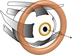
The DMI method was developed to overcome one big disadvantage of the scleral search coil technique, namely the thin lead wires needed to connect the coil to the recording apparatus. These wires are prone to breakage and pose thus an enormous risk, especially in animal studies (re-implantation). Instead of employing a small coil embedded in a small rubber annulus the DMI method makes use of a golden ring that is placed on the subject’s eye. The subject is seated in a primary magnetic field that induces an AC-current in the ring which creates a small secondary magnetic field. This field can be picked up by a coil placed in close vicinity in front of the ring. The coil can then be connected to the recording hardware without any difficulties.
Making use of secondary induction to get rid off the vulnerable wires comes at a price. The ring signal decays exponentially with distance so that it is very important to position the pickup coil as close as possible to the eye. The exact geometry of ring and pickup coil influences the signal. When the center of rotation of ring and coil are aligned the linear range is symmetrically restricted to about +/-10 deg and even becomes non-monotonic beyond about +/-30 deg as can be seen in figure 1 (solid line; for comparison the SSC signal is plotted as a dashed line). In practice it is not always possible to achieve a perfect alignment of ring and pickup coil. This will lead to a shift of the linear/non-monotonic range making the calibration of the signal somewhat tedious. In addition to this the pickup coil will also pick up the much stronger primary magnetic field. In order to cancel this primary contribution a second coil is needed that is connected in anti-parallel to the pickup coil. The SSC signal on the other hand can easily be described by a sine with a linear range that covers the whole oculomotor range (Fig. 1 dashed line). It is also quite easy to record in head-unrestrained paradigms. Because of the relative cumbersome implementation and its restriction to head-restrained paradigms the DMI method has not been used widely.
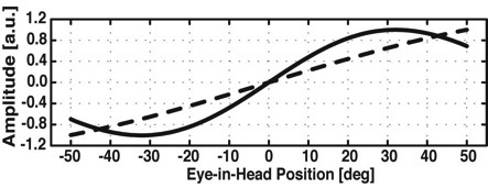
Fig. 1 Simulation of the DMI (solid line) and the scleral search coil signal (dashed line) for horizontal only eye movements. Note that the DMI signal becomes non-linear beyond +/-10 deg while the search coil signal is still monotonic.
We have recently described the theoretical background (Bremen et al. 2007B) needed to extend the DMI method to 2D head-unrestrained gaze measurements and tested our calibration routine with human subjects (Bremen et al. 2007D). Two extensions were necessary that make the method straightforward to use. First, an additional frontal primary magnetic field, perpendicular to the horizontal and vertical fields helps to disambiguate the signal. This can be seen in figure 2. For each head orientation there exists an unique combination of the horizontal (solid line) and the frontal (dashed line) signals (denoted by the filled dots connected by grey vertical lines). Theoretically it is possible to measure a full circle of 360 deg. The same holds obviously for the vertical signal making 2D recordings possible. Therefore, all that is needed for calibration are the horizontal, vertical and frontal DMI signals as well as the head orientation (for example obtained with a coil). However, remember that the exact geometry of the ring and pickup coil determines the location of the linear and non-monotonic range (compare for example H=0 deg with Fig. 1). Second, since this misalignment is hard to quantify in before hand and the use of micro-manipulators to align ring and pickup coil is quite cumbersome (and likely not perfect) we opted for a parameter-free calibration with artificial neuronal networks (ANNs).
Extension to 2D head-unrestrained gaze measurements

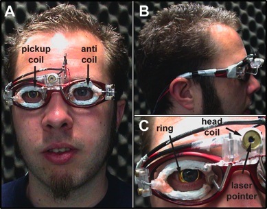
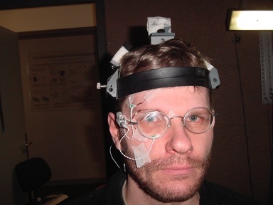
Fig. 4 Our technician, Stijn Martens, wearing the custom-build DMI assembly and the golden ring. The assembly holding pickup coil, anti-coil and laser pointer is made from a light-weight sunglasses frame. Note that the coils a insulated with silicon rubber in order to insulate them. A Frontal view. B Side view. C Close up of ring, pickup coil and laser pointer. Note that a small coil is wound around the pointer. This coil can be used to record head movements.
last modified Jan 01 2009
Fig. 2 Simulated DMI signals for three different head-orientations (H), horizontal eye movements only. The horizontal and frontal field signals are denoted by the solid line and the dashed line, respectively. The ring’s center of rotation is slightly shifted relative to the pickup coil. Note that the linear range for H=0 deg is between to about 0 and +20 deg (compare with Fig. 1). Note also that the combination of horizontal, frontal field signals and head orientation yield unique combinations (black dots connected by vertical grey lines). The complicated ring signal can thus be disambiguated.
A B
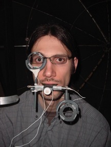
Fig. 3 Two developmental stages of the DMI assembly. A Me wearing the mobile bit-board inspired by the one used for head-restrained measurements. It caused tremendous vibration artifacts in the vertical channel. Additionally it was not fun to wear for an hour during a typical recording session. B Rob with pickup coil and anti-coil directly taped to his skin. The primary field remnant was gigantic with this assembly because the two coils did not have the same orientation in the primary magnetic fields so that cancellation was far from perfect. Note that the glasses we were wearing did not create a magnetic field.
For human subjects we developed a calibration routine in which the subject has to first fixate a LED with a head fixed laser pointer and then make eye movements while keeping the head still. In this way points on the curves depicted in figure 2 can be sampled. This calibration paradigm is rather intricate and although humans after being instructed perform very well animal subjects need to be trained before performing adequately. Therefore, I am currently developing a calibration paradigm that only requires the fixation of randomly distributed targets. This task is readily learned by animal subjects and has been used extensively in oculomotor studies. Currently, I employ simulations of the oculomotor system and the DMI signal to determine the optimal number of targets, target locations and ANN settings. Subsequently, I test my predictions by performing experiments with human subjects.
The ANN approach has another advantage: the networks take small in-homogeneities of the primary magnetic field into account and even more important the remnant primary signal. Due to small electrical and geometrical differences between the pickup coil and the anti-coil in practice it is not possible to perfectly cancel the primary field signal. This primary remnant can be described as a head-dependent DC-offset (Bremen et al. 2007B). Although the size of this remnant does not pose a problem for the networks it can be problematic for the AD-conversion. The ring signal is usually quite small and you want to adjust your conversion range accordingly. However, if the primary remnant is a tenfold or even hundredfold bigger than the DMI signal you are limited in your possibilities.
In order to minimize the remnant primary signal we had to experiment a bit. Our technician build several prototypes according to our specifications of the - as we call it - DMI assembly (frame that holds the pickup coil and anti-coil). We wanted to have a frame that yields the best cancellation possible, is light-weight and is easy to build and use. We started out with a mobile version of the bite-board used with the classical head-restrained DMI method (Fig. 3A). However, as you can surely imagine this thing is not very comfortable; especially when you have to bite on it for an hour (a typical recording session with the DMI method can last that long). In addition, it was not very aerodynamic impeding your head movements and even worse it introduced enormous vibration artifacts in the vertical channel. Cancellation per se was quite okay though. After having done one of those tiresome experiments we thought: Keep it simple! We just taped the pickup coil and anti-coil to our skins (Fig. 3B). But - and we could have known this in before hand - cancellation was really bad. Although the coils were electrically quite similar the angle between the two coils was enormous. They therefore picked up a different amount of field lines. We forgot about this attempt very quickly since we finally came up with a sunglass frame on which the two coils could be mounted (Fig. 4). This DMI assembly yields the best results according to the above mentioned criteria and doesn’t it look cool?
